Time stretch can be readily analysed by modelling the band-pass optical signals with low-pass complex envelopes. The transfer function of the dispersive element in the time-stretch system, H(ω), is mainly a phase propagator:
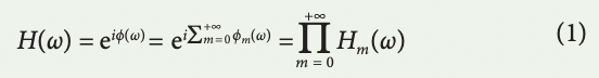
in which ϕ(ω) is the phase profile of the group delay dispersion28, and its range can reach 106 radians. ϕm(ω) are the phase modes resultant from the expansion of the phase function space in a basis set. The transfer function can be viewed and implemented as a cascade of mode operators, Hm(ω). The group delay profile of this propagator, τ(ω), is
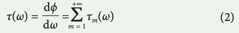
where τm(ω) are the group delay modes of the cascaded operators. Assuming the optical carrier frequency is at ωc, the down-converted spectrum of an optical pulse with complex envelope Ei (t) is denoted by E ~ i (ω = ωo – ωc), where ωo is the optical frequency and ω is the modulation frequency. On propagation through the timestretch system, the pulse is reshaped into a temporal signal with a complex envelope given by
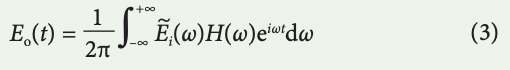
Using stationary phase approximation, which is satisfied when filter group delay is relatively large leading to the far-field regime of dispersion, only the frequency component ω contributes to the signal at time t according to the relation t = τ(ω) and equation (3) is estimated as
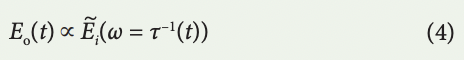
which means the spectrum is mapped to time with the group delay profile. τ–1(t) is the inverse function of the mapping described by equation (2), and it can be nonlinear. Only if the group delay profile is linear, τ(ω) = τ0ʹω + τ0 (the group delay dispersion is constant), equation (4) is simplified as
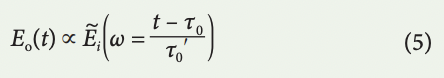
where τ0 is the time of arrival at the photodetector for the carrier frequency, ωc, and the mapping of the spectrum to time is uniform. This is the regime called time-stretch dispersive Fourier transform (TS-DFT). The spectral resolution, corresponding to the ambiguity in frequency-to-time mapping26,126, is approximately
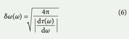
Resolution scales inversely with the amount of group delay dispersion. In coherent time stretch (also known as time-stretch spectral interferometry), an interferometer splits the pulse into two arms with delay of τd with respect to each other. Once these two copies of the pulse are recombined, an interference pattern is formed in the output of the interferometer, which embeds the pulse phase information:
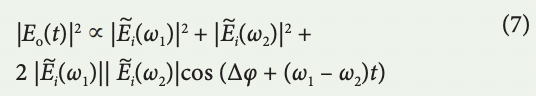
in which, ω1 = τ–1(t), ω2 = τ–1(t – τd), and the difference of the input pulse phases at these two frequencies is contained in Δφ, forming time-stretch adaptation of spectral shearing interferometry. The time-stretch interferogram can be captured by an ADC, providing complex field acquisition in single shot, but in a continuous fashion. The accuracy of the complex field measurement would be bound by the spectral resolution given by equation (6) and by the ENOB of the ADC.
NATURE PHOTONICS, JUNE 2017 is available here. (PDF opens in a new tab)